Resource Centers
Lean Manufacturing Layout Options
Process flow and layout are at the heart of lean manufacturing.
- In all cases, the flow patterns arrange the process steps in a natural flow order, link process steps to minimize cycle time and travel distance, eliminate crossover points, and simulate a continuous flow process by putting internal customers and suppliers next to each other.
Each layout option has advantages and disadvantages.
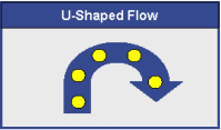 U-shaped flow is perhaps the most common flow configuration to implement. A U-shaped configuration allows the work cell to be laid out using a fairly small footprint.
- A straight-through (or an I-shape flow) is often the best flow pattern for long, narrow buildings.
- L-shaped flow configurations may work best for square-shaped buildings when several similar process lines are nested together.
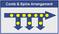 The comb and spine arrangement works well for assembly operations when products must exit the process flow at various levels of assembly.
- While each flow pattern has advantages, all, except the comb and spine, are variations of the straight-through flow. Other common variations on the straight-through pattern include the S-shaped and M-shaped patterns used to compress the footprint of long process flows.
Which layout is best for your operation?
- While the U-shaped flow is arguably the most common layout for lean, other flow patterns can be used just as effectively.
- The layout shape used for any given workflow will most likely be a function of facility constraints and accommodation of other workflows rather than a pressing requirement for a specific flow pattern.
- Process flow considerations, physical site constraints, and the location of utilities all play a role in determining the facility-wide flow pattern and layout locations at a macro facility level.
Process flow considerations
Product Families
- One of the first challenges of dispersing functional process equipment into a simulated continuous flow process is determining which equipment should be used for which lines.
- A dedicated line producing just one product is only feasible when the product volume requires the entire capacity for the line.
- More often than not a process line is used to manufacture a family of products.
Cubic Feet (Bulk) Handled
- When determining at a macro level where in the facility a process line should be located, consider the bulk of the product produced on the line.
- Locate lines producing bulky products close to manufacturing entry and exit points to minimize the material handling requirements.
Use of Shared Equipment and Resources
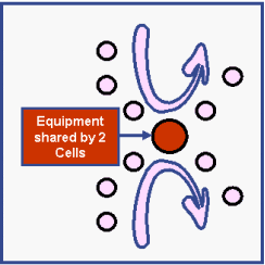 If two or more workflows will share a common piece of equipment or resource, the layout for those processes must include easy access to that shared equipment or service.
- Shared equipment does present challenges beyond layout and location issues; protocols for scheduling and handling priorities need to be addressed as well.
Use and Role of Feeder Cells
- When planning the layout of a process workflow involving a complex assembly, the use of feeder cells to supply modules or subassemblies to a main assembly line is an effective lean manufacturing approach.
Impact of Purchased (Offsite) Services
- Some in-process tasks may be contracted to outside suppliers such as plating, anodizing, or heat treating operations.
- The need to outsource can add another layer of complexity as schedules must be adapted to meet supplier schedules; as a result, the process may need to be treated as two separate workflows.
Physical site constraints
Location of Entry and Exit Points
- The entry and exit points, specifically the location of the receiving and shipping docks, play a significant role in both the shape of the layout and placement of the various workflows.
Building Height and Floor Loading
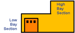 Building height is a major constraining factor for locating workflows within the facility.
- Obviously, processes that require high bay space must be given priority for placement in the high bay section of the facility and heavy equipment cannot be placed in areas not rated for the load.
Location of Process Monuments
- A process monument is a unit or piece of equipment that cannot or should not be moved. As the layouts for workflows are developed, the process must come to the monument.
The location of monuments is a major factor in determining where processes must be located.
Location of utilities, facilities, and maintenance access:
- Before selecting a specific layout for a workflow, confirm that needed utilities and facilities are available to the planned locations, forklift and personnel traffic can be routed effectively, and the equipment is accessible for maintenance.